Blog Details
How Hydraulic Thread Sealing Works: NPT, BSPP, SAE ORB, Metric and JIC Connections Explained
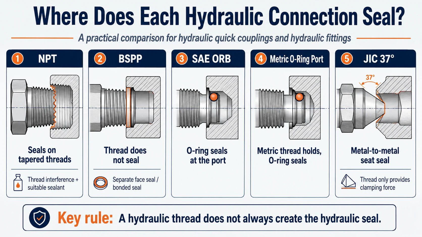
A hydraulic connection can have perfectly matching threads and still leak if the wrong sealing method is used. The reason is simple: the thread does not always create the hydraulic seal.
On an NPT joint, the tapered threaded engagement forms part of the sealing system and the specified installation practice normally includes a suitable sealant. On a BSPP connection, the parallel thread usually supplies clamping force while a washer, O-ring, cone, or face seals outside the thread. SAE O-ring boss and many metric ports seal with an elastomer at a machined port. A JIC connection seals at a 37° metal seat.
Knowing where the pressure boundary is created changes how a leak should be diagnosed. More torque or more tape cannot repair every hydraulic connection and can make the damage worse.
1. Thread Engagement and Fluid Sealing Are Separate Functions
A threaded hydraulic joint must normally perform two functions:
- Mechanical retention: the threads hold the fitting in the port and maintain assembly load.
- Fluid sealing: a defined interface prevents pressurized fluid from escaping.
Some connections combine these functions within a tapered threaded joint. Others deliberately separate them. With SAE ORB, for example, the straight thread retains the fitting while the O-ring forms the pressure seal. With JIC 37°, the thread pulls two metal seats together but is not the sealing surface.
2. Quick Comparison: Where Each Connection Seals
| Connection | Thread form | Where the pressure seal occurs | What the thread primarily does |
|---|---|---|---|
| NPT | Tapered, 60° | Within the tapered threaded joint using the specified sealant and assembly practice | Creates interference and retention |
| BSPP | Parallel, 55° | At a separate washer, O-ring, cone, or defined face | Provides retention and clamping force |
| SAE ORB | Parallel UN/UNF, 60° | At the O-ring and machined port chamfer/counterbore | Provides retention |
| Metric O-ring port | Parallel metric, 60° | At the O-ring and specified metric port geometry | Provides retention |
| JIC 37° | Parallel Unified, 60° | At the mating 37° metal cone and flare seats | Pulls the metal seats together |
This comparison covers common connection principles, not every fitting design. BSPP and metric thread designations do not by themselves define the sealing interface; the complete port or fitting standard must also be known.
3. How NPT Thread Sealing Works
NPT means National Pipe Taper. General-purpose NPT dimensions and gauging are defined by ASME B1.20.1. The male and female threads taper, so flank interference increases as they are assembled.
Where NPT seals
The threaded engagement is part of the pressure boundary. Standard NPT threads have a helical leak path at the crest and root clearances, so hydraulic assembly commonly requires a compatible sealant and the installation method specified by the component manufacturer.
The sealant fills microscopic flow paths; it does not correct the wrong pitch, damaged threads, insufficient engagement, a cracked female port, or incompatible materials.
NPT is not the same as NPTF
NPTF is a Dryseal pipe-thread system with different crest/root interference requirements. Do not assume an NPTF designation, gauging method, or sealant instruction applies to an NPT component. Verify the drawing and standard specified for both parts.
Typical NPT leak causes
- wrong thread system, such as NPT assembled with BSPT;
- damaged, dirty, or galled threads;
- sealant incompatible with the fluid or temperature;
- too little or too much engagement;
- excessive torque that distorts or cracks the female port;
- sealant fragments entering the hydraulic circuit.
Use only an approved sealant and follow the fitting or equipment manufacturer’s preparation, engagement, torque, and cure instructions. Do not add tape or paste to an unidentified connection.
4. How BSPP Connections Seal
BSPP means British Standard Pipe Parallel and is normally marked with G, such as G1/2. ISO 228-1 defines this 55° parallel pipe-thread family for connections where pressure-tightness is not created by the threads themselves.
Where BSPP seals
The thread holds the parts together. The pressure seal occurs at a separate feature defined by the complete connection, which may include:
- a bonded seal under a shoulder or hexagon;
- a captive O-ring at the port face;
- an elastomeric or metal washer;
- a specified cone or internal sealing face.
That is why “G1/2” is not a complete sealing specification. Two G1/2 components can have matching threads but incompatible seats or sealing elements.
Typical BSPP leak causes
- missing, reused, hardened, or cut bonded seal;
- wrong washer or O-ring dimensions;
- scratched, corroded, painted, or uneven sealing face;
- incorrect stud end for the port geometry;
- side load or misalignment preventing even compression;
- overtightening that damages the seal or deforms the seat.
Thread tape on a BSPP thread does not replace the specified face seal. If a BSPP joint leaks, inspect the actual sealing surface first.
5. How SAE O-Ring Boss Sealing Works
SAE O-Ring Boss, usually abbreviated ORB, uses a straight Unified thread and an elastomeric O-ring. SAE J1926 defines common straight-thread O-ring ports and stud ends used in hydraulic fluid power.
Where SAE ORB seals
The O-ring is compressed in the defined space between the male stud end and the machined port chamfer/counterbore. The straight thread retains the fitting and maintains the assembly position.
Because the O-ring forms the pressure seal, pipe-thread tape or paste is not the primary sealing mechanism and should not be used as a substitute for the correct O-ring.
Typical SAE ORB leak causes
- cut, twisted, pinched, extruded, or missing O-ring;
- incorrect O-ring size, hardness, or material;
- damaged lead-in chamfer or sealing counterbore;
- dirt or metal chips across the O-ring path;
- dry assembly when the specified procedure requires lubrication;
- incorrect adjustment or locknut procedure on an adjustable stud end;
- pressure, temperature, or fluid outside the seal’s capability.
Replace the O-ring with the exact specified size and compatible compound. An O-ring that looks similar can still have the wrong cross-section, hardness, swell resistance, or temperature range.
6. How Metric Hydraulic Connections Seal
A designation such as M22×1.5 describes the metric thread diameter and pitch. It does not define where the connection seals.
Common metric hydraulic sealing designs include:
- metric straight-thread O-ring ports, including ISO 6149-type arrangements;
- bonded-seal or washer connections;
- 24° cone fitting systems;
- other manufacturer- or standard-specific face seals.
Metric O-ring port
In a metric O-ring port, the thread provides retention while the O-ring seals against the specified port geometry. The principle resembles SAE ORB, but the thread dimensions and port specifications are different.
Metric 24° cone
In a 24° cone connection, sealing occurs at the cone interface or at the sealing element defined by that fitting system. The metric thread supplies clamping force.
Typical metric connection leak causes
- identifying only M diameter and pitch while ignoring the seat;
- mixing a metric O-ring stud with a different metric port design;
- damaged O-ring, cone, tube end, or sealing face;
- incorrect assembly sequence or torque;
- confusing M22×1.5 with the visually similar G1/2 BSPP thread.
7. How JIC 37° Sealing Works
JIC hydraulic fittings use a 37° flared connection commonly associated with SAE J514. The fitting uses straight Unified threads, but those threads do not contain the fluid.
Where JIC seals
The pressure seal occurs where the male 37° cone contacts the female 37° flare or seat. Tightening the nut draws the two metal surfaces together and creates the required contact load.
Thread sealant on the straight threads cannot repair a scored, cracked, misaligned, or mismatched 37° seat.
Typical JIC leak causes
- scratch, dent, corrosion, or contamination on the cone or flare;
- cracked or poorly formed tube flare;
- misalignment that prevents uniform metal contact;
- mixing 37° JIC with a different seat angle or sealing design;
- undertightening that does not establish contact load;
- overtightening that deforms the seat or damages the tube flare;
- vibration or unsupported tubing applying cyclic side load.
8. BSPT and Other Tapered Pipe Threads
BSPT uses a tapered 55° Whitworth pipe thread, commonly designated R for an external taper and Rc for an internal taper under ISO 7-1. Like other pressure-tight tapered pipe-thread systems, the thread joint and specified sealing practice form the pressure boundary.
BSPT is not interchangeable with NPT. Both are tapered, but their thread form and pitch differ. A pair that engages for one or two turns can still be unsafe and leak under pressure.
9. The Seal Material Must Match the Fluid and Temperature
Correct geometry is not enough when an elastomer is part of the seal. O-ring and bonded-seal material must be selected for:
- hydraulic fluid and additives;
- minimum and maximum temperature;
- working and transient pressure;
- decompression rate and pressure cycling;
- ozone, weather, cleaning chemicals, or fire-resistant fluids;
- required hardness, compression set, and extrusion resistance.
NBR, FKM, EPDM, HNBR, and other compounds are not universal substitutes. For example, a material suitable for mineral hydraulic oil may not be suitable for a phosphate-ester fluid. Use the equipment or seal manufacturer’s compatibility data for the actual fluid formulation and temperature.
10. Hydraulic Connection Leak Diagnosis Workflow
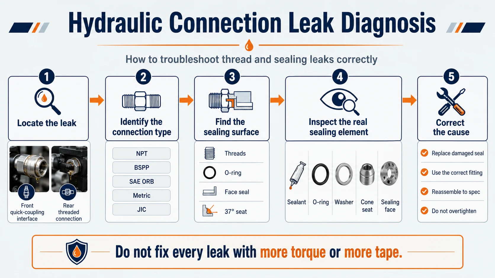
Step 1 — Make the system safe
Shut down and isolate the equipment, relieve stored pressure, support loads, and allow hot components to cool. High-pressure hydraulic fluid can penetrate skin. Never search for a leak with a bare hand. Follow the machine manufacturer’s approved leak-detection procedure.
Step 2 — Locate the actual leak
Clean the area and determine whether oil originates from:
- the front quick-coupling interface;
- the rear threaded connection;
- the hose-to-fitting interface;
- the coupling body, sleeve, or valve;
- an adjacent component that is allowing oil to track along the assembly.
A leak seen below the thread may have started at the coupling face and migrated along the hexagon.
Step 3 — Identify the complete connection
Record taper or parallel, diameter, pitch, thread form, sealing feature, and part number. Use the Hydraulic Quick Coupling Thread Identification Guide when the connection is unknown.
Step 4 — Find the real sealing surface
Decide whether the fluid should be retained by tapered threads, an O-ring, a bonded washer, a cone, a flare, or a flat face. Do not disassemble further until the intended pressure boundary is understood.
Step 5 — Inspect the sealing element and mating surface
Look for cuts, flattening, extrusion, chemical swell, cracking, scratches, dents, corrosion, contamination, misalignment, and deformation. Check the port and fitting—not only the replaceable seal.
Step 6 — Correct the cause and reassemble to specification
Use the correct fitting, seal, lubricant, sealant, orientation, and torque procedure from the manufacturer. Replace damaged components rather than hiding the symptom with additional torque.
Step 7 — Verify safely
Restore pressure using the approved test procedure, inspect from a safe position, and confirm that the connection remains dry through the required pressure and operating cycle.
11. Leak Symptoms and Likely Inspection Points
| Observed symptom | Likely inspection area | Do not assume |
|---|---|---|
| Oil appears around an NPT port | Thread identity, engagement, damage, approved sealant, cracked port | More torque will always stop it |
| Oil appears under a BSPP hexagon | Bonded seal/O-ring and flat sealing face | The parallel thread needs tape |
| Oil appears at an ORB stud | O-ring, port chamfer, counterbore, adjustment procedure | The straight thread should be sealed |
| Metric fitting fits but leaks | Complete metric port/seat standard and sealing element | M diameter and pitch define the seal |
| Oil appears behind a JIC nut | 37° cone/flare, alignment, tube support | Sealant on the threads will repair the seat |
| Oil appears at the coupling sleeve | Front interface seals, valve, body, pressure condition | The rear port is the source |
12. Why More Torque Can Make a Leak Worse
Torque is not a sealing method by itself. It creates assembly load, but excessive load can:
- crush or extrude an O-ring;
- split a cast or machined female port;
- distort a coupling body and affect valve movement;
- deform a 37° flare or cone;
- damage threads and make disassembly difficult;
- flatten a bonded seal beyond its useful compression range.
Use the torque and assembly method specified for the exact material, size, coating, seal, port, and fitting design. Generic torque values should not be transferred between connection families.
13. When Thread Sealant Is and Is Not Appropriate
| Connection | Is thread sealant the primary seal? | Correct focus |
|---|---|---|
| NPT | Commonly part of the specified assembly practice | Approved sealant, correct engagement, undamaged matching threads |
| BSPP | No | Specified washer, O-ring, cone, or face |
| SAE ORB | No | Correct O-ring and port geometry |
| Metric O-ring port | No | Correct O-ring, stud end, and metric port |
| JIC 37° | No | Clean, aligned, undamaged 37° seats |
Uncontrolled tape or excess compound can enter valves, orifices, and servo components. Use only the product, amount, and application method approved for the identified connection and hydraulic system.
14. Replacement Checklist
Before replacing a leaking quick coupling or rear fitting, confirm:
- front quick-coupling profile and nominal body size;
- rear thread standard, diameter, pitch, and sex;
- actual sealing method and port geometry;
- seal size, hardness, and material;
- working pressure, pressure impulse, and temperature;
- fluid and cleaning-chemical compatibility;
- flow requirement and acceptable pressure drop;
- material, coating, and corrosion exposure;
- manufacturer’s assembly and torque procedure.
For a broader comparison of the rear-thread families, see the hydraulic thread type and selection guide. To measure and distinguish an unknown connection, follow the step-by-step coupling thread identification workflow. For replacement of the complete coupling, use the Hydraulic Quick Coupling Interchange Guide.
15. Frequently Asked Questions
Do hydraulic threads always seal the fluid?
No. NPT uses the tapered threaded joint as part of the seal. BSPP, SAE ORB, many metric connections, and JIC rely on a separate sealing surface or element.
Should BSPP threads use PTFE tape?
BSPP threads normally provide retention rather than the pressure seal. Use the washer, O-ring, cone, or face specified by the complete connection design instead of treating BSPP like NPT.
Does SAE ORB need thread sealant?
Normally no. SAE ORB seals with an O-ring at the port. Inspect the O-ring and machined port surfaces and follow the specified assembly procedure.
Where does a JIC fitting seal?
At the mating 37° metal cone and flare surfaces. The straight thread supplies clamping force.
Does M22×1.5 tell me which seal to use?
No. It identifies metric diameter and pitch. The complete port or fitting standard is needed to determine whether the connection uses an O-ring, washer, cone, or another seal.
Why does a new O-ring still leak?
The O-ring may be the wrong size, hardness, or material; it may have been cut during installation; or the port chamfer, sealing land, and mating part may be damaged or incorrect.
Can I stop a hydraulic leak by tightening the fitting more?
Only if the identified connection’s specified procedure shows that the assembly is under-tightened. Blindly adding torque can damage the seal, seat, thread, port, or coupling body.
16. Sealing Summary
Diagnose the sealing interface before choosing the repair:
- NPT: inspect the matching tapered threads, engagement, damage, and approved sealant practice.
- BSPP: inspect the separate washer, O-ring, cone, or face.
- SAE ORB: inspect the O-ring, port chamfer, and counterbore.
- Metric: identify the complete connection design; the M thread alone does not define the seal.
- JIC 37°: inspect the metal cone/flare surfaces and alignment.
The key troubleshooting rule is straightforward: find the real pressure-sealing surface before changing torque, sealant, or parts.
Reference standards: ASME B1.20.1 for NPT; ISO 228-1 for BSPP; ISO 7-1 for BSPT pipe-thread joints; SAE J1926 for straight-thread O-ring boss ports and stud ends; ISO 6149 for metric straight-thread O-ring ports; SAE J514 for 37° flared connections. Use the current edition and the component manufacturer’s drawing and assembly instructions for final verification.
Latest Blog