Blog Details
Quick Connect and Disconnect Couplings: Operation and Safety Guide
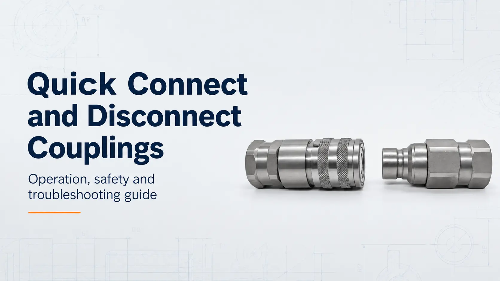
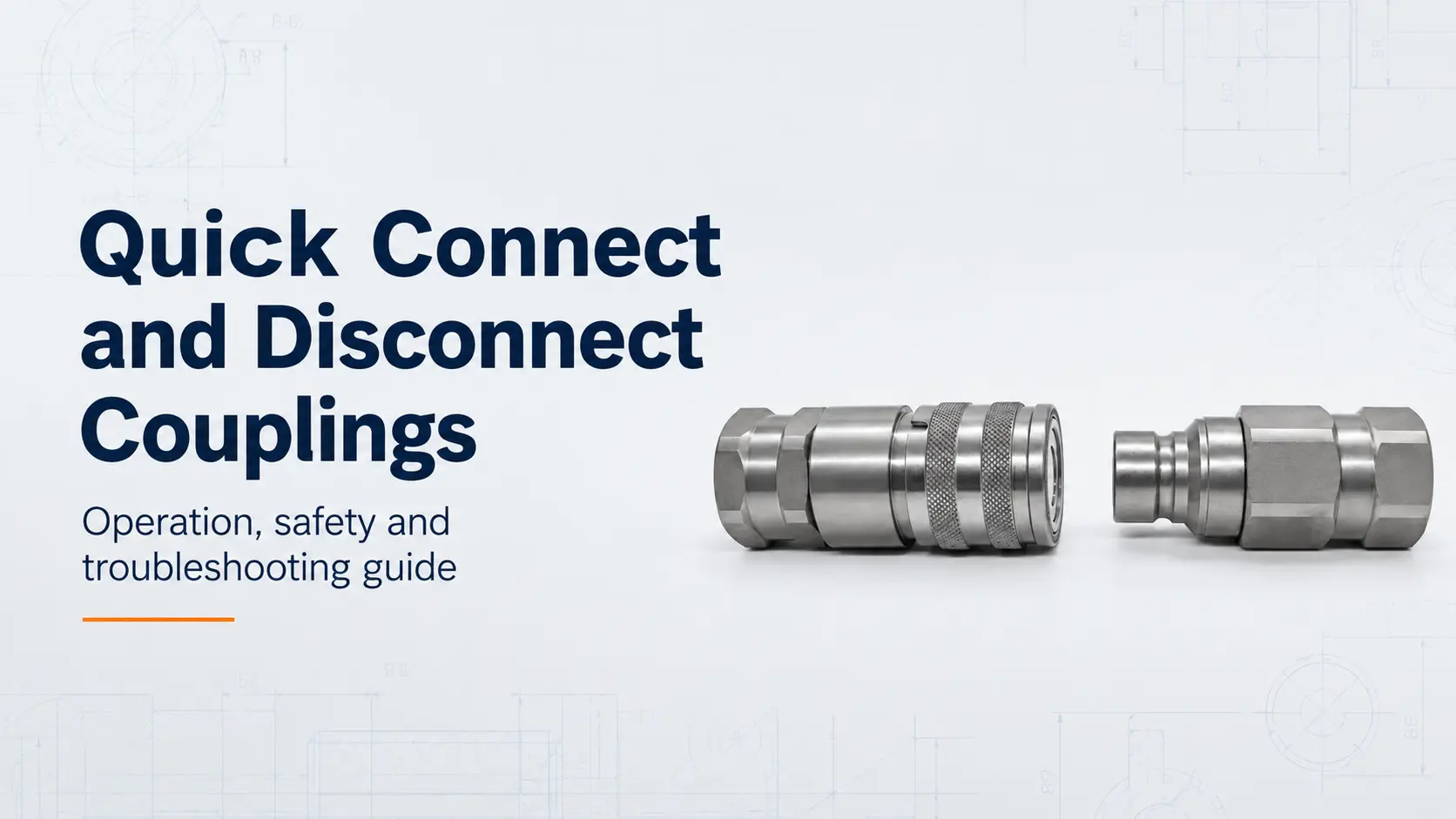
Quick connect and disconnect couplings allow a hydraulic hose, tool or machine attachment to be installed or removed without dismantling threaded pipe connections. Their speed and convenience do not remove the need for correct operating procedures.
Residual pressure, contamination, incomplete locking, damaged seals and unsupported hoses can cause connection failure, leakage or accidental separation. This guide explains how hydraulic quick couplings work, how to connect and disconnect them safely, and how to troubleshoot common problems.
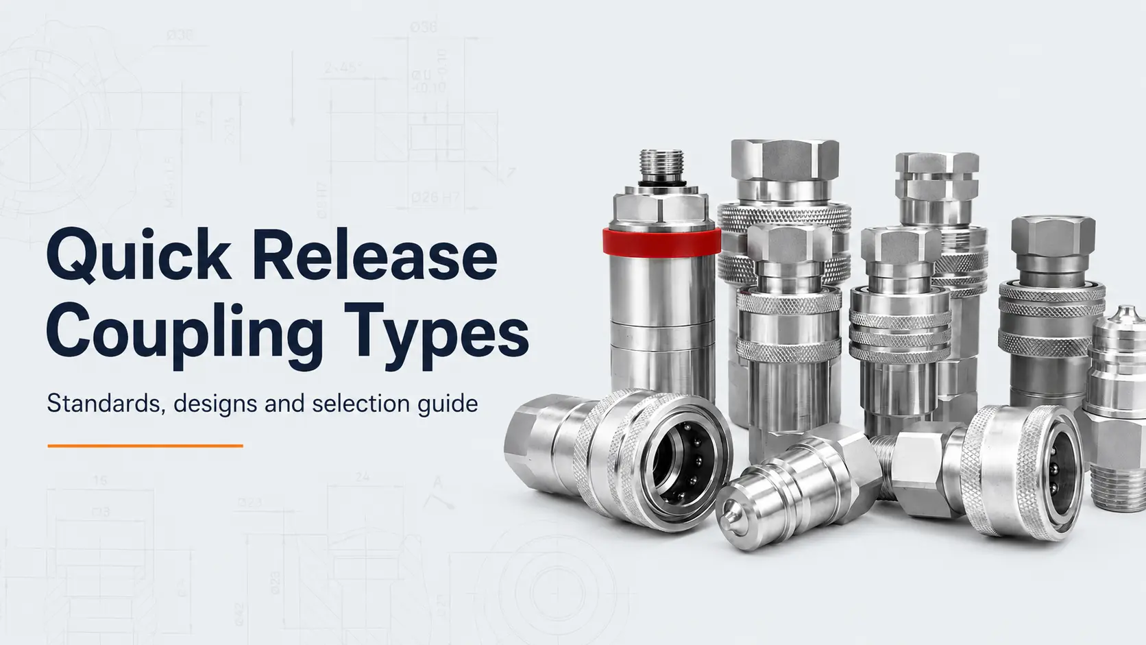
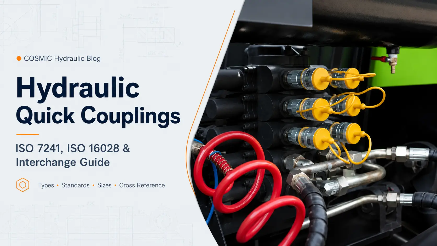
For a comparison of interface standards and coupling structures, read our Quick Release Coupling Types: Standards and Selection Guide.
What Is a Quick Connect and Disconnect Coupling?
A hydraulic quick coupling normally consists of:
- A female half, also called a socket, coupler or body;
- A male half, also called a plug, nipple or probe.
When connected, the coupling provides mechanical retention, a sealed fluid path and automatic opening of the internal valves. When disconnected, shut-off valves normally close to reduce fluid loss and limit contamination entering the circuit.
Not every quick coupling contains automatic shut-off valves. Straight-through couplings remain open when separated and require separate isolation of the fluid line.
Main Components of a Hydraulic Quick Coupling
- Coupling body;
- Male plug;
- Sliding sleeve or threaded locking nut;
- Locking balls or other locking elements;
- Locking groove;
- Poppet or flat-face valve;
- Valve spring;
- Main seal and backup ring;
- Rear connection thread;
- Dust cap or dust plug.
How a Hydraulic Quick Coupling Works
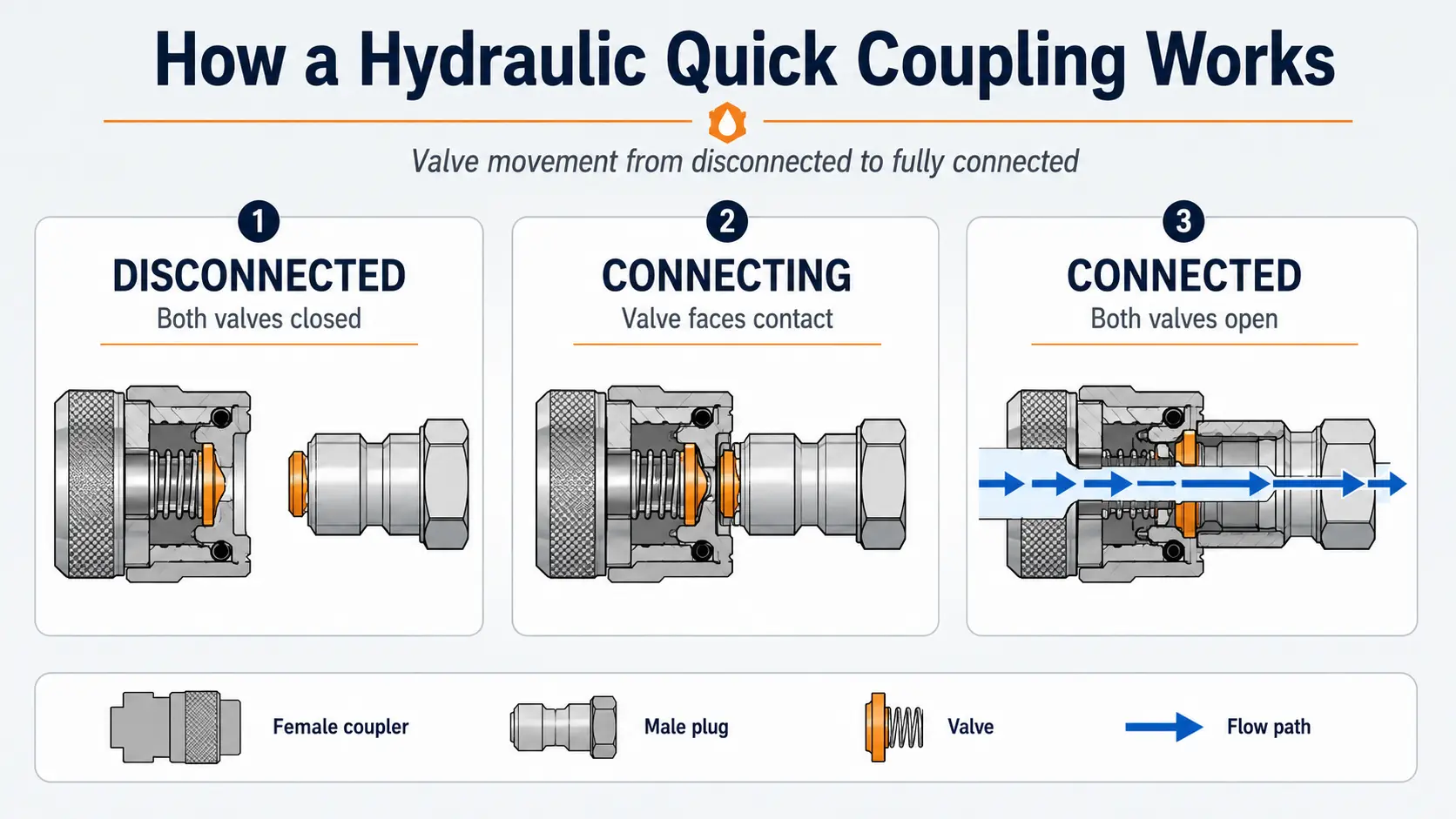
During connection
- The sleeve is retracted or the connection mechanism is operated;
- The male plug enters the female socket;
- The valve faces contact;
- Further insertion compresses the valve springs;
- The valves move away from their seats and open the flow path;
- The locking elements engage with the male plug;
- The sleeve or locking nut reaches the fully locked position.
During disconnection
- System pressure is relieved;
- The sleeve or threaded lock is released;
- The locking elements disengage;
- The two halves begin to separate;
- The internal valves return to their seats;
- The sealing interface separates after the valves have closed;
- The two halves are fully disconnected and protected with matching hydraulic coupler dust caps.
How Flat-Face Couplings Work
Flat-face couplings use flush or nearly flush valve surfaces. During connection, the valve faces contact and move inward together. During disconnection, the valves return toward their closed positions before the faces separate.
This structure reduces trapped oil, limits air inclusion and allows the surfaces to be wiped clean. ISO 16028:2023 defines interface dimensions and basic requirements for standardized flush-face hydraulic quick-action couplings.
The ISO interface does not automatically mean that every product can connect under residual pressure. This capability must be confirmed for the specific model.
Before Connecting a Hydraulic Quick Coupling
1. Stop and stabilize the machine
Stop the hydraulic power source and place the equipment in a stable condition. Lower or mechanically support attachments that could move when pressure is released.
2. Relieve hydraulic pressure
Follow the machine manufacturer's shutdown procedure. After the power source is stopped, operate the relevant controls as instructed to release pressure trapped between valves and connection points.
3. Confirm compatibility
Verify that both halves use the same mating standard, nominal size and locking profile. Also confirm pressure rating, valve structure, body material and seal compatibility.
4. Inspect both halves
Check for damaged locking grooves, deformed sleeves, corrosion, worn threads, cut seals, contamination and loose hose fittings.
5. Clean the mating surfaces
Use a clean, lint-free cloth. Dirt introduced through the coupling can damage pumps, valves and actuators.
6. Support the hose
Position the hose so that its weight does not apply side load to the coupling. Do not twist the hose or use it as a handle.
Safe Connection and Disconnection Procedure
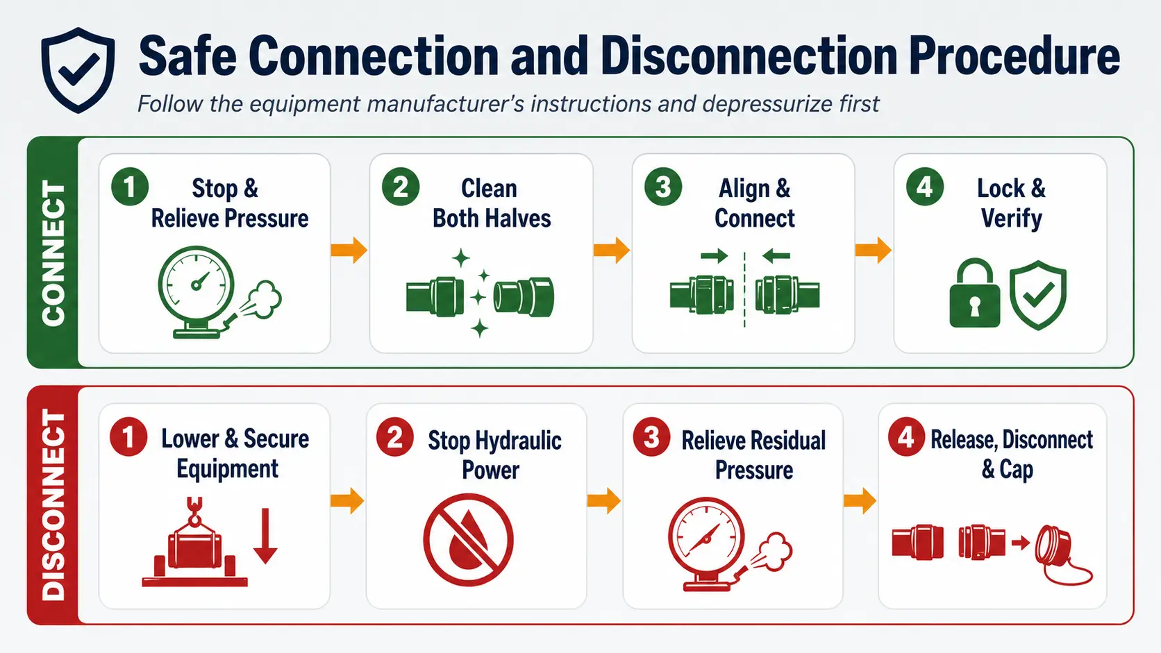
How to Connect a Ball-Lock Hydraulic Coupling
- Depressurize the system. Stop the power source and release residual pressure using the approved equipment procedure.
- Clean both halves. Remove dirt, moisture, metal particles and hardened oil.
- Retract the sleeve. Some push-to-connect designs do not require manual sleeve retraction; follow the actual product design.
- Align the plug and socket. Keep both halves on the same centerline.
- Insert the male plug fully. Do not connect at an angle.
- Release the sleeve. Confirm that it returns completely to the locked position.
- Verify engagement. Pull the plug lightly without operating the sleeve.
- Restore pressure gradually. Check for leakage, abnormal movement and hose strain.
Never use your hand to search for a high-pressure hydraulic leak.
How to Connect a Flat-Face Coupling
- Relieve pressure on both sides;
- Wipe both flat faces completely clean;
- Align the coupling halves;
- Operate the sleeve as required;
- Push the male half fully into the female half;
- Confirm that the sleeve has returned;
- Pull lightly to verify locking;
- Restore pressure gradually and inspect the connection.
Because the flat valve faces have relatively large effective areas, moderate trapped pressure can create substantial connection resistance. Do not hit the plug, use tools to force it into the socket or damage the valve to release pressure.
How to Connect a Screw-to-Connect Coupling
- Stop and depressurize the system;
- Clean the mating faces and threads;
- Align both halves;
- Start the thread by hand;
- Rotate the sleeve or nut smoothly;
- Continue to the specified fully connected position;
- Check that the thread is not crossed or partially engaged;
- Pressurize gradually and inspect for leakage.
How to Disconnect a Hydraulic Quick Coupling
- Lower and secure the equipment. Support anything that could move when pressure is released.
- Stop the hydraulic power source.
- Relieve pressure. Follow the approved equipment procedure.
- Support the coupling body. Do not pull on the hose.
- Release the lock. Retract the sleeve or unscrew the locking nut.
- Separate the halves in alignment. Avoid side loading.
- Inspect for abnormal leakage.
- Install dust protection immediately.
Why a Hydraulic Coupler Will Not Connect
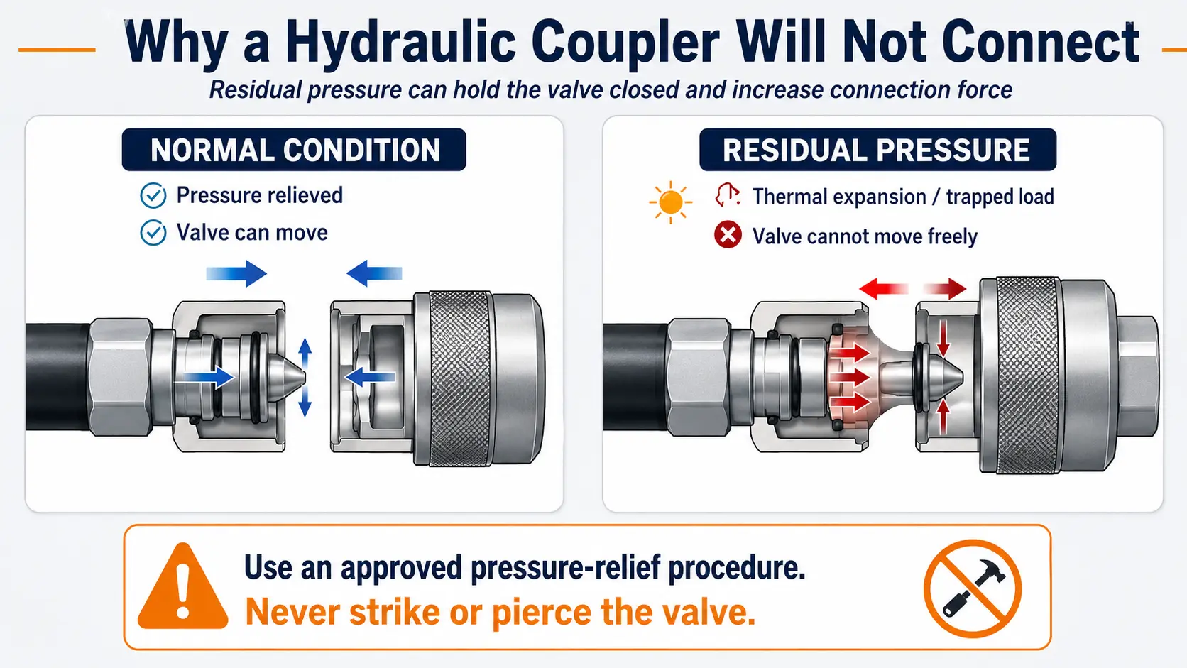
Residual pressure in the hose or attachment
Oil trapped in a disconnected hose can expand when temperature rises. The pressure acts on the valve area and creates a force that prevents the valve from moving.
Residual pressure on the machine side
An accumulator, check valve, control valve or suspended load can maintain pressure at the machine connection point.
Incompatible mating profiles
Couplings with similar outside diameters can use different nose lengths, groove positions, valve depths and locking profiles.
Contamination
Dirt around the sleeve, locking balls or valve face can prevent full movement.
Mechanical damage
A bent plug, damaged locking groove, deformed sleeve or corroded surface can block connection.
Incorrect alignment or hose loading
Side load and hose tension can prevent the plug from entering the socket concentrically.
Safe Ways to Manage Residual Pressure
Residual pressure must be managed according to the machine and coupling manufacturer's instructions. Common approved measures include stopping the hydraulic power source, lowering attachments, moving controls through the required positions, allowing hot equipment to cool and using a designed pressure-relief device.
Do not strike the valve, press it against a dirty metal surface, loosen a pressurized hose fitting, use pliers to force the halves together or place your hands near a suspected pressure-release point.
Why a Quick Coupling Leaks
Damaged main seal
A scratched plug or contaminated surface can cut or wear the main seal during repeated connection cycles.
Incorrect seal material
The seal can swell, harden or lose elasticity if it is incompatible with the fluid or temperature.
Contaminated valve seat
Particles on the seat can prevent the valve from closing completely after disconnection.
Damaged plug surface
Corrosion, scoring or impact damage can create a leakage path.
Side loading
An unsupported hose can distort the connection and accelerate seal wear.
Incomplete connection
If the plug is not fully inserted, the valve can remain partially open and the seal may not be positioned correctly.
Excessive pressure
Operating above the rated working pressure can damage seals, valve components and the coupling body.
Why a Coupling Disconnects Unexpectedly
- Incomplete sleeve engagement;
- Worn locking balls;
- Damaged male locking groove;
- Sleeve contamination;
- Incorrect mating profile;
- Excessive axial hose load;
- Contact between the sleeve and surrounding equipment;
- Pressure impulse beyond the product capability;
- Incorrect push-pull mounting.
After an unexpected separation, remove the coupling from service until the cause has been identified.
Hydraulic Quick Coupling Safety
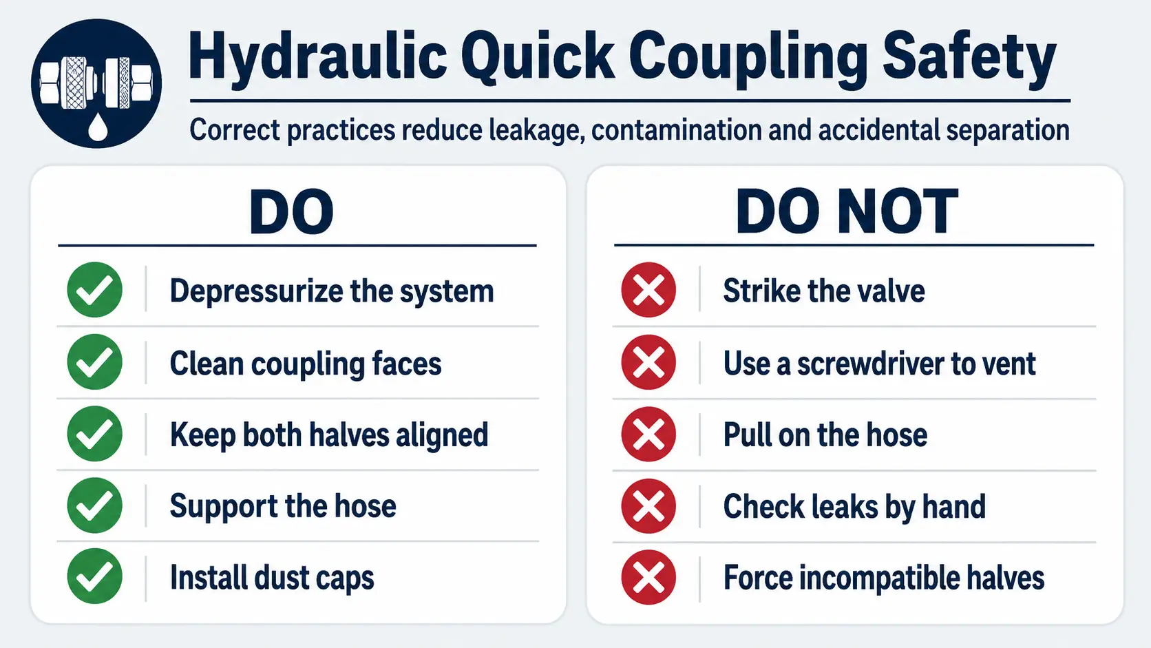
Quick Coupling Troubleshooting Table
| Problem | Possible cause | Recommended action |
|---|---|---|
| Coupling will not connect | Residual pressure | Depressurize using the approved machine procedure |
| Coupling will not connect | Incorrect mating profile | Verify the interface standard and plug dimensions |
| Sleeve will not move | Dirt, corrosion or mechanical damage | Isolate, clean and inspect the coupling |
| Leakage while connected | Damaged main seal or plug surface | Replace the seal or coupling and inspect alignment |
| Leakage after disconnection | Contaminated or damaged valve seat | Clean and inspect the valve |
| Excessive pressure drop | Coupling too small or valve restriction | Review flow requirement and pressure-drop data |
| Unexpected separation | Incomplete locking or worn components | Inspect the sleeve, locking balls and plug groove |
| Coupling becomes hot | Excessive flow restriction | Verify bore size, flow rate and valve design |
| Frequent seal failure | Misalignment or side load | Improve hose routing and support |
| Difficult disconnection | System remains pressurized | Stop the system and relieve pressure |
Inspection and Maintenance
Before each connection
- Check cleanliness;
- Inspect for corrosion and impact damage;
- Confirm smooth sleeve movement;
- Check the visible seal condition;
- Inspect threads and hose strain.
Replace the coupling when
- The plug is bent or deeply scored;
- The locking components are worn;
- The sleeve does not return fully;
- The body is cracked or deformed;
- Leakage continues after correct servicing;
- Threads are damaged;
- The coupling has been exposed to pressure above its rating;
- An accidental separation has damaged the interface.
Frequently Asked Questions
Should a hydraulic quick coupling be connected while pressurized?
Only when the specific product is designed and rated for connection under residual or operating pressure. Standard couplings should normally be depressurized first.
Why does a coupling become difficult to connect after sitting in the sun?
Fluid trapped in the hose can expand as temperature rises and create residual pressure behind the valve.
Is a small amount of oil normal during disconnection?
A small amount may be normal for conventional poppet-valve designs. Flat-face and low-spill couplings normally release less oil.
Can pressure be released by pushing the valve with a screwdriver?
No. This can damage the valve, introduce contamination and release high-pressure fluid unpredictably.
Can different brands be connected?
Only after confirming the mating interface, dimensions, working pressure, flow performance, materials and seal compatibility.
Need Help Identifying or Troubleshooting a Coupling?
Send COSMIC Hydraulic clear photos of the male and female halves, plug dimensions, connection thread, equipment model, fluid, working pressure, peak pressure, required flow and a description of the problem.
Contact COSMIC Hydraulic for identification and technical support
Latest Blog