Blog Details
Quick Release Coupling Types: ISO Standards, Sizes and Selection Guide
Quick release couplings allow hydraulic and other fluid lines to be connected or separated without dismantling threaded fittings. They are also called quick disconnect couplings, quick couplers, quick connects or QRCs.
Couplings that look similar can use different mating profiles, valve structures, locking mechanisms and pressure ratings. A matching thread size does not prove that two halves are interchangeable. Correct selection therefore requires a review of the complete application, including pressure, flow, fluid compatibility, leakage control, residual pressure and operating environment.
How Quick Release Couplings Are Classified
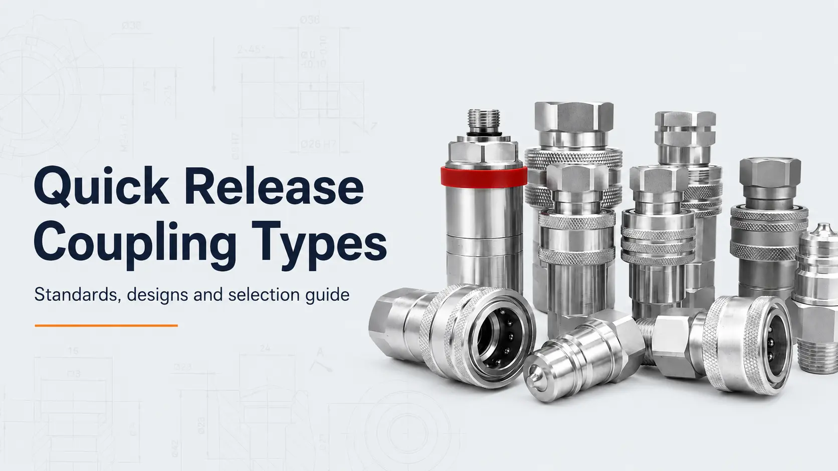
Quick couplings can be classified by their mating interface, internal valve, locking mechanism, pressure range and intended application. For engineering and purchasing work, the most useful categories are:
- Poppet-type ball-lock couplings;
- Flat-face couplings;
- Push-pull agricultural couplings;
- Screw-to-connect couplings;
- High-pressure hydraulic couplings;
- Straight-through couplings;
- Pneumatic quick couplings.
Quick Coupling Type Comparison
| Coupling type | Typical construction | Main advantages | Main limitations | Common applications |
|---|---|---|---|---|
| Poppet ball-lock | Sliding sleeve, locking balls and spring-loaded poppet valves | Compact, economical and fast to operate | More trapped oil and air inclusion than flat-face designs | General industrial and mobile hydraulics |
| Flat-face | Flush male and female valve faces | Low spill, easy cleaning and reduced air inclusion | Usually larger and more expensive | Construction machinery, attachments and clean hydraulic systems |
| Push-pull | Panel-mounted or sleeve-operated agricultural design | Convenient one-hand operation; suitable for frequently changed implements | Residual pressure and mounting arrangement require attention | Tractors, harvesters and agricultural implements |
| Screw-to-connect | Threaded sleeve or nut draws both halves together | Secure under vibration and pressure impulse | Slower connection; threads must remain clean | Mining, heavy mobile equipment and demanding hydraulic circuits |
| High-pressure | Compact reinforced body, often with threaded locking | Suitable for hydraulic tools and very high working pressure | Flow capacity can be limited in smaller sizes | Jacks, bolt tensioners, torque tools and test systems |
| Straight-through | No automatic shut-off valves | Low pressure drop and high flow | Line must normally be isolated before disconnection | Water, coolant and low-pressure transfer |
| Pneumatic | Lightweight sleeve-lock construction | Fast and easy operation | Not normally suitable for hydraulic pressure | Compressed-air tools and automation |
1. Poppet-Type Ball-Lock Couplings
Ball-lock couplings are among the most common hydraulic quick coupling designs. The female half contains locking balls around the socket body. When the sleeve is retracted, the balls move outward and allow the male plug to enter. When the sleeve returns, the balls engage with the locking groove on the plug.
Spring-loaded poppet valves open after the two halves are fully connected and close when they are separated. This construction offers a practical balance of compact size, operating speed, availability and cost.
Typical advantages
- Fast manual connection and disconnection;
- Compact and economical construction;
- Wide range of sizes and rear-port threads;
- Available in carbon steel, stainless steel and brass;
- Suitable for general industrial and mobile hydraulic systems.
Typical limitations
Conventional poppet couplings normally trap a small amount of oil between the valve faces. This oil can be released during disconnection, while a small volume of air can enter during reconnection. Where spill and contamination control are critical, a flat-face design is usually more appropriate.
2. Flat-Face Quick Couplings
Flat-face couplings use flush or nearly flush valve surfaces. The faces can be wiped clean before connection, and the design reduces the volume of oil trapped between the male and female halves.
ISO 16028:2023 specifies interface dimensions and basic requirements for standardized flush-face hydraulic quick-action couplings. A coupling described as “flat-face” is not automatically ISO 16028 compatible; the actual mating profile and product specification must be confirmed.
Why flat-face couplings are selected
- Lower fluid loss during disconnection;
- Reduced air inclusion during connection;
- Easy-to-clean mating surfaces;
- Improved contamination control;
- Good suitability for construction and attachment-change applications.
Flat-face couplings are commonly used on skid-steer loaders, excavator attachments, forestry equipment, utility vehicles and other mobile hydraulic machinery. For equipment-specific replacement work, review the available Bobcat replacement quick coupler families and verify the exact model and mating profile before ordering.
3. Push-Pull Agricultural Couplings
Push-pull couplings simplify frequent tractor-to-implement connection. Depending on the design, the female half can be mounted in a bracket or panel so the operator can connect the male tip by pushing it into the coupler.
Some agricultural couplers provide breakaway functionality, allowing the hose to separate under abnormal pulling force rather than transferring the full load to the hose assembly. Breakaway performance must be confirmed from the specific product data; it should not be assumed from appearance alone.
4. Screw-to-Connect Couplings
Screw-to-connect couplings use a threaded sleeve, nut or wing nut to draw the two halves together. The progressive mechanical engagement provides strong retention and can help in systems exposed to vibration, pressure impulse and severe mobile-duty conditions.
Typical applications
- Mining machinery;
- Oilfield equipment;
- Heavy construction equipment;
- Hydraulic presses;
- Large mobile hydraulic systems.
The threaded sleeve must be fully engaged. Partial engagement can restrict valve opening, increase pressure drop or damage the threads.
5. High-Pressure Quick Couplings
High-pressure couplings are designed for hydraulic tools and systems operating above the normal range of general-purpose mobile couplings. They frequently use threaded locking because the internal separating force rises rapidly with pressure and effective area.
Select these couplings by their rated working pressure, not by burst pressure. The hose, fittings, adapters and tool ports must have compatible ratings.
ISO 7241-A vs ISO 7241-B vs ISO 16028 vs ISO 5675
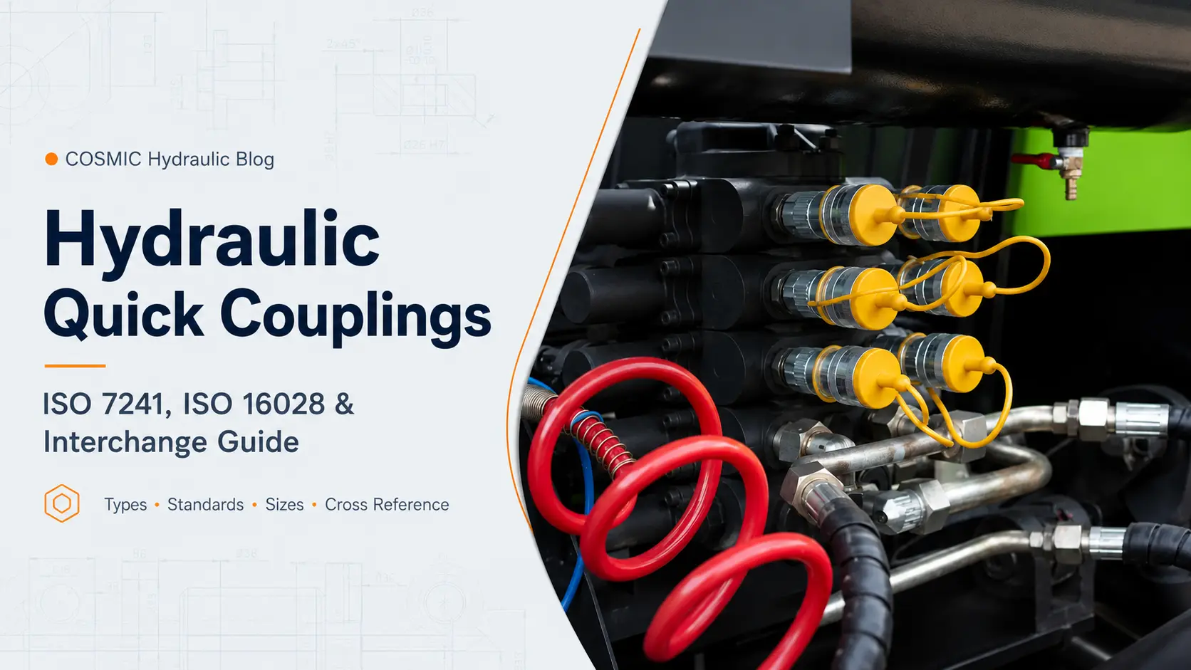
ISO 7241:2023 defines interface dimensions and basic performance requirements for two hydraulic quick-coupling series. Series A is used predominantly in Europe and is widely preferred for agricultural and forestry machinery. Series B is used predominantly in North America and in the chemical industry.
ISO 5675:2021 specifies essential interface dimensions and operating requirements for hydraulic couplers used to transmit hydraulic power from agricultural tractors to agricultural machinery, excluding braking circuits.
| Standard / series | General design | Common use | Key point |
|---|---|---|---|
| ISO 7241 Series A | Poppet-type ball-lock interface | Industrial hydraulics, agriculture and forestry | Different mating profile from Series B |
| ISO 7241 Series B | Poppet-type ball-lock interface | Industrial hydraulics and fluid-processing applications | Not interchangeable with Series A |
| ISO 16028 | Flush-face interface | Construction equipment and clean mobile hydraulics | Low-spill standardized flat-face profile |
| ISO 5675 | Agricultural tractor coupler requirements | Tractor-to-implement hydraulic systems | Application-specific agricultural requirements |
Are ISO 7241-A and ISO 7241-B interchangeable?
No. Series A and Series B use different mating dimensions and plug profiles. Even where two products conform to the same interface standard, the buyer must still compare working pressure, flow capacity, pressure drop, temperature range, body material, seal material and valve configuration.
Is ISO 5675 the same as ISO 7241-A?
They are related but not identical descriptions. ISO 7241 defines standardized quick-coupling series. ISO 5675 addresses the operating and installation requirements of agricultural tractor couplers. Many agricultural products use a Series A-style interface while also being intended for ISO 5675 applications.
How to Select the Correct Hydraulic Quick Coupling
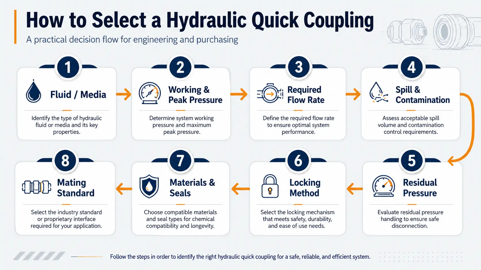
1. Identify the fluid or medium
Confirm whether the system carries mineral hydraulic oil, water-glycol fluid, synthetic fluid, water, coolant, compressed air or a chemical medium. The fluid determines the appropriate body material and seal compound.
2. Determine working and peak pressure
Review normal working pressure, maximum system pressure, transient peaks and pressure-impulse frequency. Do not select a coupling from burst pressure alone.
3. Confirm the required flow rate
A coupling that is too small can cause excessive pressure drop, heat generation, reduced actuator speed and higher energy consumption. Use the manufacturer's pressure-drop curve at the actual flow rate and fluid viscosity.
4. Evaluate spill and contamination requirements
Choose a flat-face coupling where low spill, easy cleaning and reduced air inclusion are priorities. A conventional poppet coupling may be sufficient where small fluid loss is acceptable and cost is more important.
5. Check residual pressure
Thermal expansion, suspended loads and trapped oil can leave pressure behind a disconnected valve. Standard couplings can become difficult or impossible to connect under these conditions. Residual-pressure or connect-under-pressure capability must be explicitly stated for the product.
6. Select the locking method
- Ball-lock sleeve: general industrial systems;
- Push-pull: agricultural and panel-mounted systems;
- Flat-face sleeve: low-spill mobile hydraulics;
- Screw-to-connect: vibration and pressure impulse;
- High-pressure threaded type: hydraulic tools.
7. Select materials and seals
Common body materials include zinc-plated carbon steel, stainless steel and brass. Common seals include NBR, FKM and EPDM. Compatibility must be verified against the actual medium, temperature and environment.
8. Verify the exact mating profile
Before ordering, confirm the standard, nominal size, plug dimensions, locking groove, body size, rear-port thread, valve type and any existing manufacturer or part number. Rear-port thread size does not identify the front mating interface.
Common Selection Mistakes
- Selecting by external appearance only;
- Matching the rear thread but ignoring the mating profile;
- Assuming all couplings of the same nominal size connect;
- Ignoring pressure-drop data;
- Selecting by burst pressure instead of working pressure;
- Assuming every flat-face coupling can connect under pressure;
- Mixing male and female halves without verifying the standard.
Quick Coupling Size Guide: What Nominal Size Does and Does Not Mean
Nominal coupling sizes such as 1/4, 3/8, 1/2, 3/4 and 1 inch identify a size within a coupling family. They do not guarantee the same outside diameter, flow capacity, rear-port thread or mating geometry across different standards. For example, a 1/2-inch ISO 7241 Series A plug is not interchangeable with a 1/2-inch Series B or ISO 16028 plug.
Choose size from the required flow and acceptable pressure drop, then verify the exact interface. A larger rear thread does not automatically mean a larger coupling interface, and two parts described with the same inch size can still have different connection threads.
| Check | Why it matters | Evidence to collect |
|---|---|---|
| Interface family | Determines whether plug and socket can mate and lock | Standard or series, front and side photographs |
| Nominal size | Identifies the size within that family | Catalogue designation and measured profile |
| Rear connection | Determines how the coupling joins the hose or equipment | Thread standard, size and sealing method |
| Required flow | Controls pressure drop, heat and actuator speed | Actual flow rate and manufacturer pressure-drop curve |
| Pressure duty | Controls safe product rating | Working pressure, peaks and impulse frequency |
How to Identify an Existing Quick Coupling
- Depressurize and clean the connection. Follow the equipment procedure before handling the coupling, then wipe the mating faces so markings and geometry are visible.
- Record markings. Photograph any manufacturer name, series code, nominal size or pressure marking before it becomes unreadable.
- Photograph both halves. Capture front and side views of the plug and socket, including the sleeve, valve face and rear connection.
- Measure the profile. Record plug nose diameter, overall plug length, locking-groove location, sleeve diameter and rear thread with suitable measuring tools.
- Record the application. Note the equipment model, fluid, working and peak pressure, required flow, temperature and whether residual pressure remains in the line.
- Confirm against dimensional data. Compare the measurements with the proposed manufacturer drawing. Treat a brand cross-reference as a lead, not final proof of interchangeability.
For a more detailed field procedure, see How to Identify Hydraulic Quick Couplings.
Troubleshooting Common Coupling Problems
| Symptom | Possible causes | Safe next check |
|---|---|---|
| Will not connect | Residual pressure, mismatched profile, dirt or damaged locking parts | Depressurize by the equipment procedure; clean and compare the interface dimensions |
| Leaks while connected | Damaged seal, scored valve seat, contamination or incomplete engagement | Isolate the circuit and inspect the seal, face and locking position |
| Leaks when disconnected | Contaminated or damaged shut-off valve | Remove pressure and inspect the valve face; replace damaged components |
| Excessive pressure drop | Undersized coupling, restricted valve opening or contamination | Compare actual flow with the product pressure-drop curve and verify full engagement |
| Disconnects unexpectedly | Incomplete locking, sleeve damage, side load or incorrect mating half | Stop using the circuit until the locking system and matched pair are verified |
Never search for a leak with bare hands while a hydraulic circuit is pressurized. Follow the machine manufacturer's isolation and stored-energy procedure before inspection or replacement.
Manufacturing and Supplier Verification
A standard name alone does not establish the complete suitability of a coupling. Request the dimensional drawing, material and seal specification, working-pressure data, test basis and traceable part designation for the exact series being considered.
COSMIC Hydraulic's published factory and quality overview describes its CNC machining capability, OEM support, and pressure and leakage testing. For a project-specific recommendation, the application details still need to be reviewed against the selected product series rather than inferred from a general catalogue image.
Frequently Asked Questions
Which quick coupling type has the lowest fluid loss?
Flat-face couplings generally provide lower disconnection spill than conventional poppet couplings because they trap less oil between the valve faces.
Can two couplings with the same nominal size be connected?
Not necessarily. They must also share the same mating profile, dimensional standard and locking geometry.
Does the thread size identify the coupling type?
No. BSPP, BSPT, NPT and metric threads describe the rear equipment or hose connection, not the front coupling interface.
Which type is suitable for severe vibration and pressure impulse?
Screw-to-connect couplings are commonly evaluated for demanding vibration and pressure-impulse conditions because of their secure threaded retention.
Which type is commonly used on construction attachments?
ISO 16028 flat-face couplings are widely used where low spill, easy cleaning and attachment changes are important.
What information is needed for a replacement coupling?
Provide clear photos of both halves, plug diameter, overall plug length, locking-groove dimensions, rear-port thread, system pressure, required flow, fluid and any existing brand or part number.
Need Help Selecting a Quick Coupling?
COSMIC Hydraulic supplies hydraulic quick coupling solutions for industrial equipment, agricultural machinery, construction machinery, mobile hydraulics and high-pressure tools.
Send us your application, working pressure, required flow rate, fluid, connection thread and clear product photos or dimensions. We can assist with product identification, samples, quotations and OEM requirements.
Contact COSMIC Hydraulic for product support
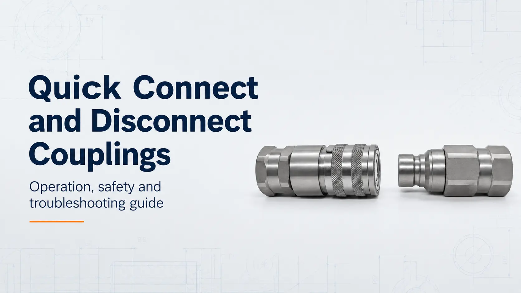
For operating and safety guidance, read our Quick Connect and Disconnect Couplings: Operation and Safety Guide.
Latest Blog