Blog Details
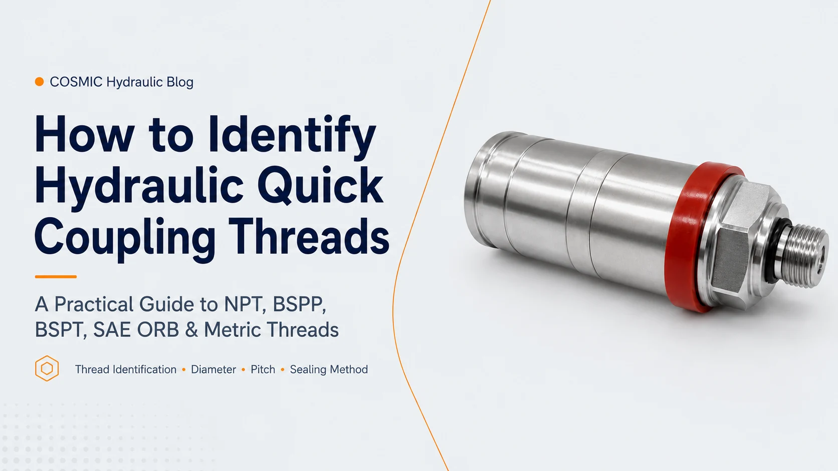
How to Identify Hydraulic Quick Coupling Threads: NPT, BSPP, BSPT, SAE ORB & Metric
An unknown hydraulic quick coupling should never be identified from a single photograph or a nominal size such as “1/2 inch.” The rear connection may be NPT, BSPP, BSPT, SAE O-ring boss, or metric, and several of these systems can look similar enough to begin threading together even when they are not compatible.
Correct identification requires a repeatable sequence: separate the front quick-coupling profile from the rear port, determine whether the thread is tapered or parallel, measure diameter and pitch, and locate the actual sealing surface.
This guide provides a field-ready method for identifying rear threads on hydraulic quick couplings before ordering a replacement, preparing a quotation, or connecting the part to a hose, adapter, valve, or manifold.
1. Identify Two Interfaces, Not One
A hydraulic quick coupling has two independent interfaces.
- Front quick-coupling interface: the male nipple and female socket profile, such as ISO 7241 Series A, ISO 7241 Series B, ISO 16028, ISO 5675, or a proprietary series.
- Rear port or termination: the connection between the coupling body and a hose, adapter, valve, manifold, or rigid line.
The front interface determines whether the two coupling halves mate. The rear thread determines whether the coupling connects correctly to the hydraulic circuit. A G1/2 rear port does not identify the front coupling series, and a 1/2-inch ISO 16028 coupling does not identify its rear port.
Record both specifications. A complete description might read:
ISO 16028 female coupler, 1/2-inch body size, G1/2 BSPP female port with bonded seal.
2. Safety Before Measurement
Do not inspect or measure a coupling while the system is pressurized. Isolate the equipment, relieve stored hydraulic pressure according to the machine procedure, verify that suspended loads are supported, and allow hot components to cool.
Clean the connection before measurement. Dirt on a thread crest can change a caliper reading, conceal damage, or contaminate the hydraulic system. Cap exposed lines after removal.
3. Tools Needed for Hydraulic Thread Identification
A basic identification kit should include:
- digital or vernier calipers;
- inch and metric thread-pitch gauges;
- a current hydraulic thread identification chart;
- good lighting and a magnifier;
- known reference fittings or certified plug/ring gauges where available;
- seat-angle gauges when cone or flare connections must be distinguished.
Calipers and pitch gauges are suitable for preliminary identification. Production inspection and final acceptance should use the gauges and tolerances specified by the relevant standard or manufacturer.
4. Hydraulic Thread Identification Workflow
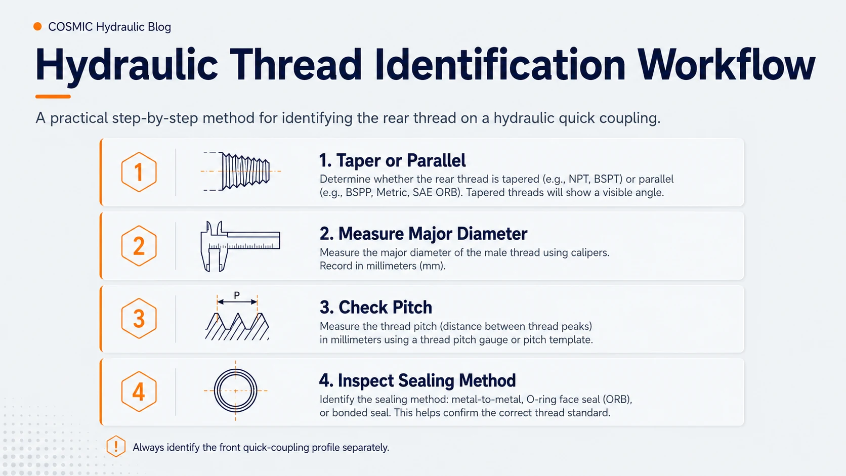
Step 1 — Record the front quick-coupling profile separately
Photograph the coupling face, locking sleeve, plug nose, locking groove, and valve. Record whether the part is the male or female half and note any standard, series, logo, or part number.
Do this before focusing on the rear thread. Matching the port while selecting the wrong front interface is a common replacement error.
Step 2 — Record all markings
Look for stamped or engraved information on the body, sleeve, hexagon, hose ferrule, or adjacent adapter. Useful evidence includes:
- manufacturer and series;
- complete part number;
- port code or dash size;
- pressure marking;
- material or seal code.
A current dimensional drawing linked to a complete part number is stronger evidence than visual similarity.
Step 3 — Determine male or female and inspect the end geometry
Record whether the rear connection has external or internal threads. Then inspect the end for an O-ring, flat sealing face, bonded washer, cone, flare seat, or other sealing feature.
The connection end often reveals the sealing system before the thread is fully identified.
Step 4 — Determine whether the thread is tapered or parallel
For an external thread, compare the diameter near the first full thread with the diameter near the hexagon. A consistent increase toward the hexagon suggests a tapered thread. Nearly equal readings suggest a parallel thread.
For an internal thread, visual assessment is less reliable. Use an appropriate gauge or compare measurements at controlled depths. Do not decide from a phone photograph alone.
Common tapered candidates include NPT and BSPT. Common parallel candidates include BSPP, SAE ORB, many JIC connections, and ISO metric threads.
Step 5 — Measure the major diameter
Measure an external thread across the crests without tilting the calipers. Take more than one reading and record where each measurement was taken. For an internal thread, use the specified internal measurement or gauge method.
Do not round the result directly to a nominal pipe size. A G1/2 or 1/2 NPT designation does not mean the outside diameter measures 0.500 inch.
Step 6 — Measure pitch
Fit a thread-pitch gauge to the thread until the teeth contact the profile without visible gaps. Inch threads are usually recorded in threads per inch (TPI); metric threads are recorded as the distance between adjacent crests in millimetres.
If a gauge is unavailable, measure across several complete pitches and divide by the number of intervals. This is only a preliminary method and is less reliable on short or damaged threads.
Step 7 — Identify the thread form and sealing method
Compare the measured diameter and pitch with a current chart, then confirm the thread form and seal. NPT and Unified/metric threads use a 60° profile; BSPP and BSPT use a 55° Whitworth profile. The actual sealing location is often the deciding clue.
Step 8 — Verify against the current standard or drawing
Before assembly or pressure testing, confirm the result against the manufacturer’s current drawing or the relevant standard. Check tolerances, engagement, port geometry, sealing element, and torque requirements—not only nominal designation.
5. Quick Comparison of Common Rear Threads
| Thread system | Typical marking | Taper or parallel | Thread angle | Primary sealing principle |
|---|---|---|---|---|
| NPT | 1/2 NPT | Tapered | 60° | Threaded joint with the specified sealant practice |
| BSPP | G1/2 | Parallel | 55° | Separate O-ring, bonded seal, washer, cone, or face |
| BSPT | R1/2 or Rc1/2 | Tapered | 55° | Pressure-tight pipe-thread joint according to the connection design |
| SAE ORB | -8 ORB / 3/4-16 UNF | Parallel | 60° | O-ring at the port chamfer |
| Metric | M22×1.5 | Usually parallel | 60° | Depends on the complete connection design |
This table is a screening tool, not a dimensional specification. Exact diameters, pitches, tolerances, and gauge requirements must come from the applicable standard.
6. How to Identify NPT Threads
NPT means National Pipe Taper. General-purpose NPT dimensions and gauging are defined by ASME B1.20.1.
Identification clues include:
- tapered male or female thread;
- 60° thread profile;
- inch pipe-size designation;
- sealing occurs within the threaded joint using the specified installation and sealant practice;
- common use on North American hydraulic equipment and hose connections.
Do not identify NPT from taper alone. BSPT is also tapered. Diameter, pitch, thread profile, and standard must agree.
7. How to Identify BSPP Threads
BSPP is a British Standard Pipe Parallel thread normally marked with G, such as G1/4, G3/8, G1/2, or G3/4. ISO 228-1 defines this parallel pipe-thread family.
Identification clues include:
- parallel thread diameter;
- 55° Whitworth thread profile;
- G designation;
- a separate sealing element or sealing face outside the threads.
On a BSPP connection, the thread normally provides retention rather than the pressure seal. Identify the bonded seal, O-ring, washer, cone, or face specified by the complete port design.
8. How to Identify BSPT Threads
BSPT refers to tapered threads in the BSP pipe-thread family. ISO 7-1 commonly uses:
- R for an external tapered thread;
- Rc for an internal tapered thread;
- Rp for an internal parallel thread used in the ISO 7-1 joint system.
BSPT uses a 55° Whitworth thread form. Its taper may make it look similar to NPT, but thread profile and pitch can differ. Treat NPT and BSPT as separate systems even when a mismatched pair begins to engage.
9. How to Identify SAE ORB
SAE O-Ring Boss uses a straight Unified thread with an O-ring that seals against the port chamfer. SAE J1926 covers this connection family.
Identification clues include:
- parallel UN/UNF thread;
- 60° Unified thread form;
- an O-ring located at the male stud end near the hexagon;
- a corresponding machined port chamfer;
- dash-size descriptions such as -6, -8, or -12 ORB.
For example, -8 ORB commonly uses a 3/4-16 UNF thread. The O-ring—not thread tape or pipe sealant—provides the pressure seal.
10. How to Identify Metric Threads
Metric screw threads are designated by nominal major diameter and pitch. In M22×1.5, the nominal major diameter is 22 mm and the pitch is 1.5 mm.
Identification clues include:
- M designation;
- dimensions recorded in millimetres;
- 60° ISO metric thread profile;
- usually parallel threads in hydraulic rear-port applications.
The thread designation alone does not define the hydraulic seal. An M22×1.5 connection may use an O-ring, bonded seal, washer, 24° cone, or another specified design. Record the complete port standard and sealing feature.
11. Common Hydraulic Thread Confusions
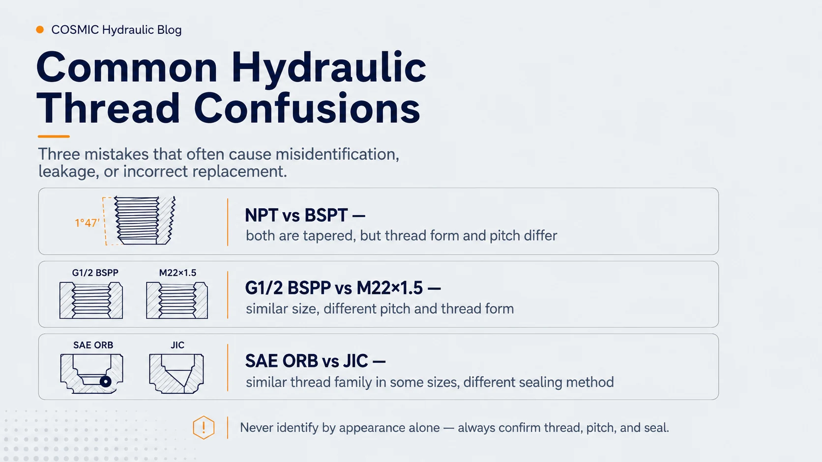
NPT vs BSPT
Both are tapered pipe threads. NPT uses a 60° profile; BSPT uses a 55° Whitworth profile. Pitch also differs in several sizes. Partial engagement is not proof of compatibility.
G1/2 BSPP vs M22×1.5
The outside diameters are close, but G1/2 uses 14 TPI (approximately 1.814 mm pitch) and a 55° profile, while M22×1.5 uses 1.5 mm pitch and a 60° profile. They are not interchangeable.
SAE ORB vs JIC 37°
Both can use straight Unified threads, and some sizes share the same thread. ORB seals with an O-ring at the port; JIC seals at a 37° cone/flare surface. Identify the sealing feature, not only the thread.
BSPP vs BSPT
BSPP G threads are parallel and use a separate sealing arrangement. BSPT R/Rc threads are tapered and belong to a pressure-tight pipe-thread joint system. The word “BSP” alone is incomplete.
12. Measurement Record for an Unknown Coupling
| Item | What to record | Why it matters |
|---|---|---|
| Front interface | Standard/series, body size, male or female half | Confirms which coupling half can mate |
| Rear connection sex | External or internal thread | Narrows the port and stud-end candidates |
| Taper | Tapered or parallel; measurement method used | Separates pipe-thread and straight-thread families |
| Major diameter | Measured value and measurement location | Provides a dimensional candidate |
| Pitch | TPI or millimetres | Distinguishes visually similar sizes |
| Thread form | 55° or 60°, if confirmed | Separates BSP from NPT/Unified/metric families |
| Sealing feature | Thread, O-ring, bonded seal, face, cone, or flare | Confirms the complete connection design |
| Markings | Manufacturer, series, part number, port code, rating | Supports drawing and cross-reference verification |
13. Worked Identification Examples
Example A — Parallel pipe thread with a bonded seal
The male thread diameter is essentially constant, the pitch matches 14 TPI, the profile is consistent with 55° Whitworth, and a bonded seal seats under the hexagon. The likely candidate is G1/2 BSPP. Confirm against ISO 228-1 dimensions and the port drawing.
Example B — M22×1.5 with an O-ring
The measured major diameter is close to 22 mm, the pitch gauge confirms 1.5 mm, and the thread is parallel. An O-ring is visible near the stud end. Record the connection as an M22×1.5 O-ring port candidate, then verify the exact port standard and O-ring geometry. “M22×1.5” alone remains incomplete.
Example C — Tapered 60° pipe thread
The diameter increases toward the hexagon, the pitch matches the NPT chart for the measured pipe size, and no separate O-ring or sealing washer is present. The likely candidate is NPT. Confirm with the correct NPT gauge and installation specification before assembly.
14. Common Identification Mistakes
- Measuring only diameter: close diameters occur across different thread systems.
- Using a ruler instead of calipers and pitch gauges: small differences determine compatibility.
- Assuming any tapered thread is NPT: BSPT is also tapered.
- Calling every straight UNF thread JIC: SAE ORB may use the same thread but a different seal.
- Calling every BSP thread G: BSPP and BSPT use different designations and joint principles.
- Ignoring the seal: thread dimensions do not fully define BSPP, ORB, JIC, or metric hydraulic connections.
- Forcing a part that starts to engage: mismatched pitch can damage both components.
- Identifying the front coupling from the rear thread: the two interfaces are independent.
15. What to Send When Requesting Identification
To obtain a reliable response from a supplier, send:
- one photograph of the complete coupling;
- straight-on photographs of the front interface and rear port;
- a side photograph showing thread length and taper;
- measured major diameter;
- measured pitch in TPI or millimetres;
- the visible sealing feature;
- all markings and the existing part number;
- system pressure, flow, fluid, temperature, and application.
Thread identification only confirms the rear connection. A replacement quick coupling must also match the front profile, size, pressure and flow capability, seal material, temperature range, and operating conditions. See the NPT, BSPP, ORB and metric thread comparison for selection context, the connection sealing and leak diagnosis guide for troubleshooting, and the Hydraulic Quick Coupling Interchange Guide for the complete replacement process.
16. Frequently Asked Questions
How can I tell NPT from BSPT?
Both are tapered. Measure diameter and pitch, identify the thread profile, and confirm with the correct gauge. NPT uses a 60° profile; BSPT uses a 55° Whitworth profile.
How can I tell BSPP from BSPT?
BSPP G threads are parallel. BSPT R/Rc threads are tapered. Their sealing arrangements and standard designations also differ.
Is G1/2 the same as M22×1.5?
No. Their diameters are close, but their pitch and thread profile are different. They must not be used as substitutes.
Does the O-ring prove a connection is SAE ORB?
No. O-rings are used in several metric and BSPP connection designs. Measure the thread and verify the complete port geometry.
Can I identify a thread from a photograph?
A photograph can narrow the possibilities, especially when the sealing feature and markings are visible. Final identification normally requires diameter, pitch, taper, and drawing or gauge confirmation.
Does matching the rear thread make two quick couplings interchangeable?
No. The front quick-coupling profile and nominal body size must also match, together with pressure, flow, fluid, seal, and application requirements.
17. Identification Summary
Use the same sequence every time:
- Record the front quick-coupling interface separately.
- Clean and safely depressurize the component.
- Record markings and sealing features.
- Determine tapered or parallel.
- Measure major diameter and pitch.
- Confirm thread form and sealing location.
- Verify the result with the current standard or manufacturer drawing.
A reliable identification is based on several agreeing observations. Never force a connection because the first threads appear to fit.
Reference standards: ASME B1.20.1 for NPT; ISO 228-1 for BSPP; ISO 7-1 for BSPT pipe-thread joints; SAE J1926 for O-ring boss ports and stud ends; ISO 68-1, ISO 261, and ISO 724 for ISO metric screw threads. Use the current edition and the component manufacturer’s drawing for final verification.
Latest Blog